December 2006

receiver success!

pc120042.JPGAfter going through the theory on the receiver circuit below, I’m pleased to report that I’ve had some success with a fairly simple little circuit that I knocked up.

After a lot of trial and error with capacitor values (which culminated in me asking the guy in Maplin for 2 of every value capacitor he had) I managed to hit upon the right combination of capacitance and inductance for me to receive a fairly good 60kHz signal, as the rather shaky mobile phone video below shows! The combination that worked for me was a 470pF in parallel with a 330pF capacitor, making a total capacitance of 800pF. The inductor (antenna) that I used was Maplin code LB12N, with all of the windings wired up in series. According to a datasheet Maplin provided for this antenna, this should equal an inductance of 3.5mH, but I’m not convinced. Hey ho – it receives the signal fine!

Click here to see a video of the receiver in action, showing the signal on my scope. The length of time that the carrier is sent (i.e. there is fairly big signal on the display) decides whether a 1 or a 0 is being sent. This results is a string of 1’s and 0’s, which can be decoded to give the current time and date.

I’ll knock up a quick diagram of the 60khz receiver circuit and post it here in the next few days, incase anyone’s interested!

Receiver Circuit

Been a little while since I’ve updated this, but I’ve been hunting down an oscilloscope to try and develop a receiver circuit, trying to work on the circuit at work (where I have access to every piece of test equipment under the sun) in my lunch breaks has proved difficult as I’m too busy at work to give it time!

I’m using a bog standard LC circuit (simply an inductor and capacitor in parallel) to pick up the 60kHz signal, by choosing certain values of inductor (L) and capacitor (C), the inductor can be made to resonate at a particular frequency, given by the equation below.  Basically, if you have the LC circuit resonate at 60kHz it’ll pass anything it receives on 60kHz into the next stage of the circuit.

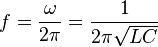
  where f=frequency (hertz), L=inductance (henrys), C=capacitance(farads)

Only a very small signal is received (sometimes only a few millionths of a volt), so this needs to be amplified before anything can be done with the signal.  I will be using a JFET for an initial amplification, which will then be fed into an op-amp.  The reason for the JFET is that it has a very high input impedance (as good as an open circuit), so none of the signal will be lost to ground, which is very important when you’re talking about millionths of a volt.

Once the signal has been amplified, it can then be rectified (turned into a DC voltage level).  I’ll probably then use a comparator to make the signal a perfect digital signal, before feeding it into an input pin of a PIC.

Due to the nature of the circuit, I probably won’t be able to build it on a breadboard (prototype board, plug board whatever you want to call it!) before putting it onto stripboard, because breadboard is famous for being useless for RF applications because of stray capacitances and inductances through the board, which make any half sensitive circuit you put on it oscillate horribly.

My local Maplin seems to have sold out of everything I need to make a suitable inductor (antenna), so the building is delayed until they get their act together and order some bits in!

Meanwhile, I’ll plan and get the amplification stages of the circuit onto some stripboard and test basic amplification functionality.