sensitive 60kHz receiver: schematic part two
 Shown on the left (click it to enlarge) is the circuit diagram for the receiver part of the clock – click it to make it readable or download it. This schematic is essentially a sensitive 60kHz receiver and ASK demodulator. You could use it as a simple receiver for other frequencies by just taking the signal at point 4 and adjusting the Inductor (antenna) and shunt capacitor to match the frequency you wish to receive.
The circuit should be fairly self explanatory. Firstly the power for the receiver comes from the PSU/decoder, and can be around 13-20V. A 7809 9v voltage regulator brings this down to 9v for our needs, there’s no need for a heatsink on the regulator if it’s the 1A type. As far as receiving the signal is concerned, the ferrite antenna and two shunt (parallel) capacitors adjust the frequency that they resonate at, according to this equation:
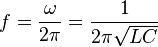
We can’t really change L, it’s set by the ferrite rod antenna (code LB12N from Maplin) Once you have found a C value to set f as 60kHz (I found C to be around 840pF), they will resonate and you’ll be receiving any 60kHz signal in the air. This signal is obviously tiny though, so we amplify it. The first stage of amplification is a JFET (2N3819). This has an extremely high input impedance, which is exactly what we want. The JFET’s gain is set to 10 by the 1k and 100R resistors. After a DC blocking capacitor there are two identical stages of op amp amplification. The gain of each op amp is set to -214 (the – indicates that there will be a phase shift, we don’t care about phase so that’s ok). Each op amp also acts as a low pass filter, attenuating frequencies higher than 72kHz, which helps us a lot.
After this we’re at point 2 in the schematic and we have a big 60kHz signal. This signal is turned into a DC level by the use of a low voltage drop diode (a germanium type would be ideal, silicon types e.g. 1n4001 are not suitable) and a 10n capacitor. The resulting DC level is then fed into a comparator, a low pass filter to weed out any fast spikes, then another comparator. The levels of each comparator can be adjusted. Simply adjust each 10k potentiometer until you get a decent signal. The LED will flash at 1Hz when a good signal is received.
The best way of setting the circuit up is by the use of an oscilloscope. If you live near Anthorn then you can ditch one of the TL081 op amps. The shunt capacitor value next to the ferrite antenna will need fiddling with to get a decent signal, and you may find that the resistors around the comparators may also need adjusting, the 10k potentiometer may not have enough adjustment for your needs.
So there you have it – the schematic for a sensitive 60kHz receiver. Feed the output of this into part one of the schematic and you’ll have a perfectly working, completely accurate clock!
The circuit could be improved significantly by ditching the germanium rectifier diode in favour of a system that does not give us a voltage loss. There are plenty of example circuits around for op amp based rectification circuits, but I didn’t have the veroboard space to try some other rectification methods.
