hurrah! it works again!
 In order to receive the now super low power signal, I had to add another amplification stage to the receiver. The new stage is identical to the first stage. I’m using a TL081 JFET input op amp, but any decent op amp will do the job (note that a 741 isn’t decent!). The op amp is set up as an inverting amplifier, R2 (feedback) is 47k, R1 is 220R. There is a 47pF resistor in parallel with R2, to turn the amplifier into a low pass filter. The 3dB cutoff point is described by the equation below:
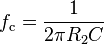
In our case, fc works out to be 72kHz, so all frequencies under this are passed, frequencies over this are attenuated.
The newly amplified signal is then fed into a diode and smoothing capacitor, as before. After this stage, a comparator is used that can be set to output high when the 60kHz time signal is present, and low when it isn’t. When the signal was being transmitted from Rugby this was the last stage of the circuit, but unfortunately now there are so many spurious pulses detected as a result of the extra amplification, that I have had to add an RC series low pass filter on the output of this comparator, to filter out any short spurious pulses. R has been set to 47k, C is 220nF. This filtered signal is then fed into yet another comparator, the output of which produces the digital pulses that comprises the time signal. Yay!
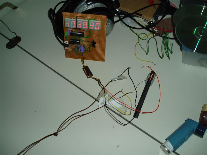
Sadly that wasn’t the end. The scan rate of my display is 330khz, that is to say that each digit is flashed on and off 330,000 times a second. This is so that many digits can be controlled with not may pins, every display segment is linked to the next one. Only one display digit is ever on at a time, but the human eye cannot see this. This display scanning creates a lot of RF interference, which leaks into my amplification stages and completely swamps the time code signal. I’d managed to make a time code signal jammer with my display. Brilliant.
In order to overcome this I tried putting the display in a screened box, but this did not help. A long bit of wire with ferrites on each end also did not help with the interference problem. In a moment of genius (even if I say so myself), I wound some old thin copper wire I had kicking about around a ferrite rod, and connected it in series with the 12v supply line between the receiver and the display. This eliminated the interfering signals enough on the line for the receiver to work as it should. Yay! So now the clock is happily sitting telling me the time, without fault.
Time to put it in a box then!