Now I’ve got to the point where the display needs to be built. True to form, I’ll be mounting the digits on stripboard. I’ll be using three double digit red LED displays, two for hours, two for minutes and two for seconds. Every segment of each digit needs to be connected to the corresponding segment on the other digits, and then to the display driver IC. This means that 48 segments need to all be interfaced and connected up to the right places, a wiring nightmare!
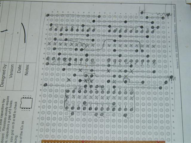
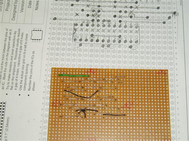
Below you’ll see an image of me working on the wiring. I have decided to wire in two modules (4 digits) first, and then just piggy back the third module off the second. It’s quite hard to explain, but when I get the wiring diagram up and sorted it should be fairly self explanatory!
The display driver and PIC are going to sit on the same board as the display. I’ll be mounting the display driver IC as close to the actual display as possible to try and minimise the effects of electromagnetic interference, something that could cripple my sensitive receiver circuit.
On a slightly different note, it’s interesting to note that the 60kHz time code transmitter is currently in the process of moving from Rugby to Anthorn (probably should have thought about that before calling this the rugby pic clock..). The transmitter at Anthorn was being tested today, but unfortunately I was at work so couldn’t check whether my receiver still worked well. It would be a bit of a bummer if the signal is now too far away to decode reliably, but I’m sure it’ll be fine!
That’s it for the time being! It’s probably all very tricky to understand at the minute, but I will get a complete schematic up soon, which should make things much simpler.