 The first thing on my to do list is to make a PIC Programmer, so that I will eventually be able to get the code I develop for decoding the time signal from my PC onto a PIC.
One of the beauties of using a PIC in this project is that all of the time code decoding and drive for the LED display is handled by firmware that I write and program to the PIC. This means that if the time code format ever changes (VERY unlikely!) or I want to change how the display works or whatever, I can easily just tweak the firmware code and program it to the PIC. This is not possible with hardware, without physically replacing components.
Another good thing about using a PIC is that it reduces the component count enormously.
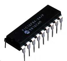
I’ve decided to use the PIC 16LF84A. This device has two ports, a 5-bit PORT A and an 8-bit PORT B. Each bit can be individually set as either input or output. I had originally intended to use a 16F84, but it turns out that these are now obsolete, but the 16LF84A is a pin for pin replacement that also uses the same programming interface as the 16F84. I’ve chosen the 16LF84A simply because it’s the only PIC device I have experience with!
As far as PIC programmers are concerned, the simplest programmer schematic I’ve found is the ironically titled No Parts PIC Programmer (NOPPP). This simple circuit uses a PC parallel port to program the 16F84. This type of circuit was what I had in mind for a programmer, finding a schematic for one that someone has tested is great! I’ve a fair amount of experience in using the parallel port to control external devices and I have to say that it’s a brilliant interface, so much easier than serial and USB communication. I’m sad to see parallel ports disappearing from PC motherboards, although I’m sure there are some USB > Parallel converters out there!
I could not find any veroboard layouts for the NOPPP, so I made my own layout, which will appear here soon!
To program a PIC you need two voltage levels, 12v and 5v. To get these levels I simply used a 7805 5v voltage regulator. The 7805 will convert 12v to 5v nice and simply, meaning that my circuit has just one voltage input, which is 12v. The circuit then uses the 12v in the parts of the circuit that need 12v, then feeds the 12v into the 7805, the 5v output of which is used in the parts of the circuit that need 5v. In order to make the stripboard layout nice and neat, I’m going to buy a PCB mounted 3.5mm mono socket, that you can connect 12v to. Easy peasy.