There are going to be three main elements to the CatTrack design:
- The microcontroller
- The narrow-band transceiver
- The GPS module
The basic architecture will look like this:
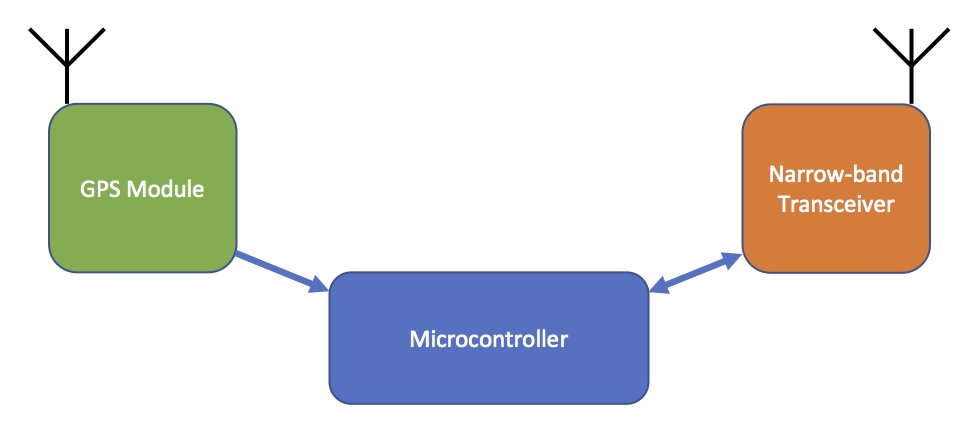
Fundamentally the way I see it working is thus:
- The collar will sit in its ultra-low-power saving mode, waiting to receive a message via the narrow-band transceiver.
- The user sends a message from the basestation to the collar, requesting the position.
- The collar instructs the GPS module to turn on.
- As soon as the collar has a GPS fix, it sends the location information back to the basestation, using the narrow-band transceiver.
There are two blue arrows in the diagram, indicating that the microcontroller will need to support two communication protocols – one to talk to the GPS module and another to talk to the narrow-band transceiver. Based on previous experience, I’ll probably end up talking to the GPS module via UART, and the transceiver via SPI, therefore it would be useful if the microcontroller I pick supported both of these protocols in hardware.
The UART protocol is fundamentally the same as RS232, the protocol carried on the old D-type connectors you see on ‘ancient’ computers! The only real difference between RS232 and UART are the voltages used. RS232 swings between negative and positive voltages in order to transmit data bits, whereas UART swings between 0V and a positive voltage. UART voltage levels are designed for communication over small distances across circuit boards, whereas RS232 signal levels are designed for communication over many metres of cable.
RS232 signals are also inverted compared to UART, but fundamentally all of the timings and control bits are exactly the same between the two. The reason I can be confident that I will be communicating with the GPS module via UART is because in my experience every single GPS module in the land supports communication with a host via UART! Many also support communication via SPI/I2C or even USB (fancy!), but all will support UART.
Any GPS module that communicates via UART will almost certainly use the NMEA 0183 data specification for framing the data. To be clear, UART is simply a way of transmitting 1s and 0s between a host (my microcontroller) and a slave device (my GPS module). You need to somehow turn those 1s and 0s into meaningful data such as your current latitude, longitude and speed etc. That’s what NMEA 0183 is for. It describes how your actual positional information is encoded. In more specific terms, the NMEA protocol is at the Application layer and the UART protocol is one below it, at the Data link or Physical layer.
Now, NMEA is a horrible, horrible protocol. The only good thing about it is that it is an ASCII protocol, so its very easy to debug. Every thing else is rubbish. It’s a convoluted mish mash of data sentences which result in the engineer having to pick out the information they are looking for from multiple sentences which have all come in at different times from each other with different timestamps. The lead developer of gpsd says that…
A mob of crack-smoking rhesus monkeys could have designed a better standard than NMEA 0183.
…and I am inclined to agree!
On previous projects in the past I have ditched the NMEA protocol and switched the GPS receiver into a proprietary binary protocol mode. This has some massive advantages, not least that it makes your code much simpler and you can just read the binary straight out of the module into a packed struct, no ASCII conversion required. I may end up using a binary protocol for CatTrack too.
SPI is the other protocol I’m likely to be using. I’ll probably end up using this protocol to talk to my transceiver IC. The protocol is designed in order to allow microcontrollers to communicate with multiple slave devices at high speed. Clock speeds greater than 40 MHz aren’t uncommon in SPI communication. It’s made up of 4 seperate lines, SCLK (a clock line), MISO (master in slave out – data moving from the microcontroller to the slave device), MOSI (data moving from the slave to the master) and CS (chip select). The idea is that you daisy chain the SCLK, MOSI and MISO lines to all of your slave devices, but route a separate CS line to each slave. When you want to talk to a specific device you select the device by driving that device’s CS line to 0V whilst leaving all the other CS lines high. You then send your data on the SCLK and MOSI lines and read the reply on the MISO line. All of the other devices know to ignore the data if their CS line hasn’t been pulled to 0V by the microcontroller. It’s a fairly simple protocol and most microcontrollers have hardware support for it.
There is another popular communications protocol that’s worth mentioning called I2C. This protocol differs from SPI in the fact that it requires only 2 lines as opposed to the 4 required by SPI. I2C relies on device addresses. The idea is that each device on the daisy chained communication lines has a different address. The first thing the microcontroller does when it wants to talk to a device is tell everyone which device address it wants to talk to. The others then know to ignore everything from that point on.
The downside with I2C is that it is significantly slower than SPI. 400 kHz is the maximum clock speed you tend to see, with some exceptions which work up to 1 MHz. You could never get close to SPI’s > 40 MHz clock speed with I2C. But then clock speed tends not to be a concern for I2C devices which tend to be things like temperature sensors or real-time clocks where you are only interested in a couple of bytes of data every few seconds. The reason I can be confident that my transceiver will use the SPI protocol is that when transmitting at high data rates you will need a clock speed greater than 400 kHz.
Now I need to get on and choose my microcontroller!
One comment