Motivation and dedication are still high!
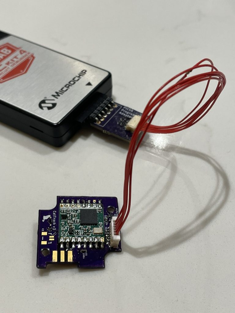
I’ve managed to complete the schematic and PCB, get it sent off to oshpark (my favourite PCB fab!), get them back, and solder them up, phew. I went for oshpark’s 0.8mm board thickness in order that my stacking heights would work inside the case, so they took a little longer to arrive than normal.
The schematic is below (click to enlarge). It’s quite simple and comprises the following:
- A MCP1700T voltage regulator, to turn the 4.2 – 3.5V of a LiPO battery to the 3.3V everything else needs.
- A PIC16LF18325 microcontroller. I always use the PIC range of microcontrollers, mostly because I’m used to them (and they’re much better than AVRs 🤪). The base current in sleep is only 30nA so it’ll suit the fact that I want to be in a super low power sleep for 99% of the time in order to conserve battery.
- A HopeRF RFM95W LoRA Transceiver. As discussed in my previous post I’ll be using this LoRA module. It is simply a convenient way of breaking out the Semtech SX1276 LoRA Transceiver.
- A small buzzer. This is a piezoelectric device and will need to be driven via a transistor at 3kHz from a PWM pin on the PIC.
- A couple of FETs for voltage monitoring. I am using an N-type FET to turn on a P-type FET in order to measure the voltage of the LiPO battery via an ADC pin on the PIC. If I had it permanently connected up to the PIC then current will be constantly wasted in the potential divider.
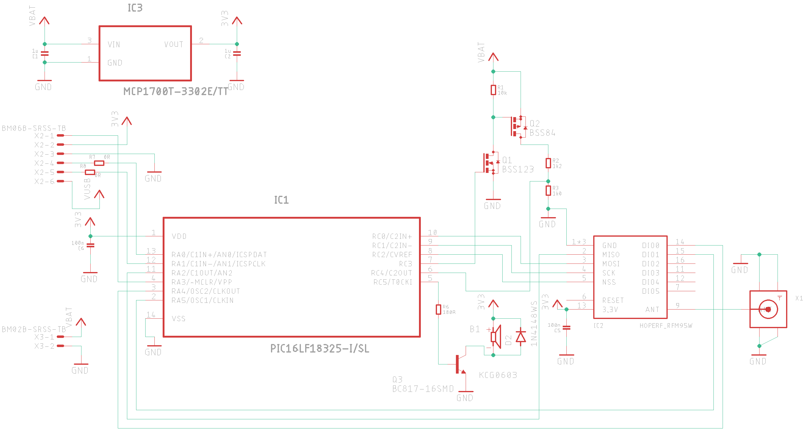
Not the neatest schematic in the world but it makes sense I think!
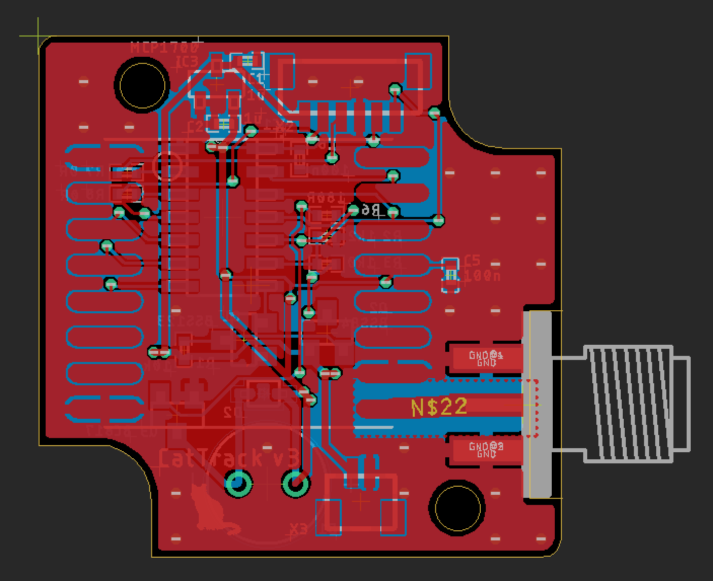
Because I know which Hammond case I’m using (the smallest of their flanged range), I imported their example dxf and simply used that as the board outline. It’s not the busiest board in the world, so it didn’t take too long to lay out. It’s a 2 layer board, which thankfully Eagle lets me lay out for free. One day I will migrate to something like KiCAD, but I just can’t be bothered yet. The next time I want to do a 4-layer board I’ll have to bite the bullet because the price of Eagle these days is absolutely insane! £66 per month! No hobbyist will ever spend that.
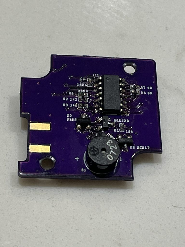
The components are mostly 0402 and the board can be powered and programmed via the 6-pin JST header I’ve added. The header will also double-up as a GPIO feed to a couple of LEDs that will sit on the outside of the case.
A new thing I’ve been doing recently is to put component values on the silkscreen. This helps soldering so much, as I never have to refer to a BoM. I can simply look at the PCB and straight away see what each component should be.
I have used MPLAB’s Code Configurator to set up the PIC pins to do what I need them to. Microcontrollers these days are so complex with all the things you need to do to set up the oscillators/timers/pin assignments etc. and the code configurators that manufacturers offer do take a lot of the faff away. The downside is that the code it generates is incredibly convoluted and complicated, but thankfully it’s still C (not C++!) and I can follow it easy enough. What I usually do is to take the relevant bits out of code it generates, but this time I might just let Microchip have their way and leave the Code Configurator generated code in there.
The first thing I wanted to do was to test the sounder. Thankfully, it worked perfectly! I used the code configurator to set the timer and PWM to a 3kHz square wave and the sound came out nice and loud. It’ll be a great help when you’re close to the cat.
In my previous post I was fearing setting all the registers up on the RFM95W (SX1276). The TI CC1101/1120 range of deviecs have so many registers that the only real way to do it is to use a bit of TI supplied software called SmartRF Studio. Thankfully the job was much easier than I had feared.
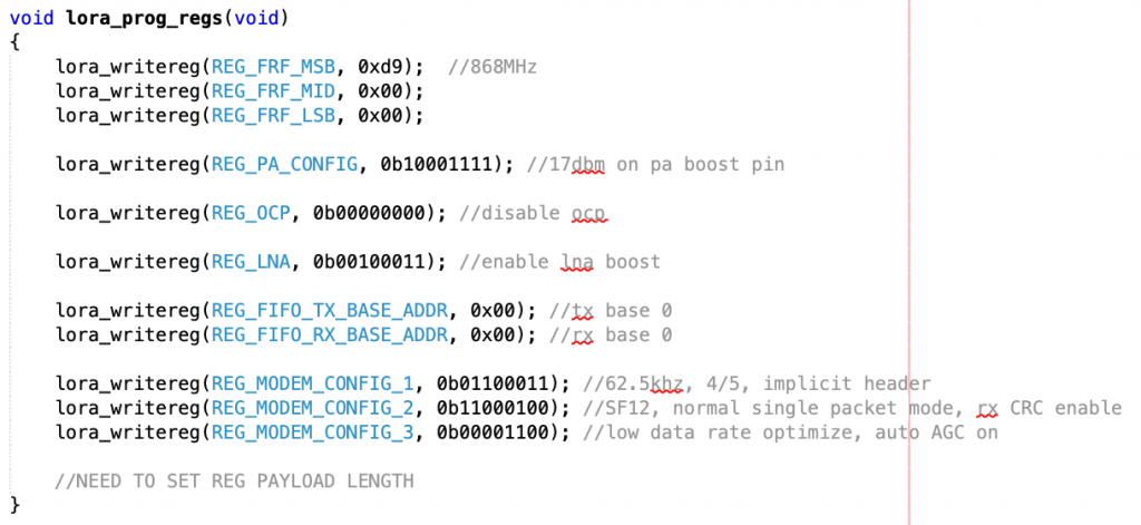
That’s the complete set of registers I need to set – hardly any faff at all, excellent!
The module seems to initialise fine, and when I call the transmit routine I’ve written it reports that the transmit was a success – a good start. I’ve not checked the RF output on a spectrum analyser yet but I will do soon.
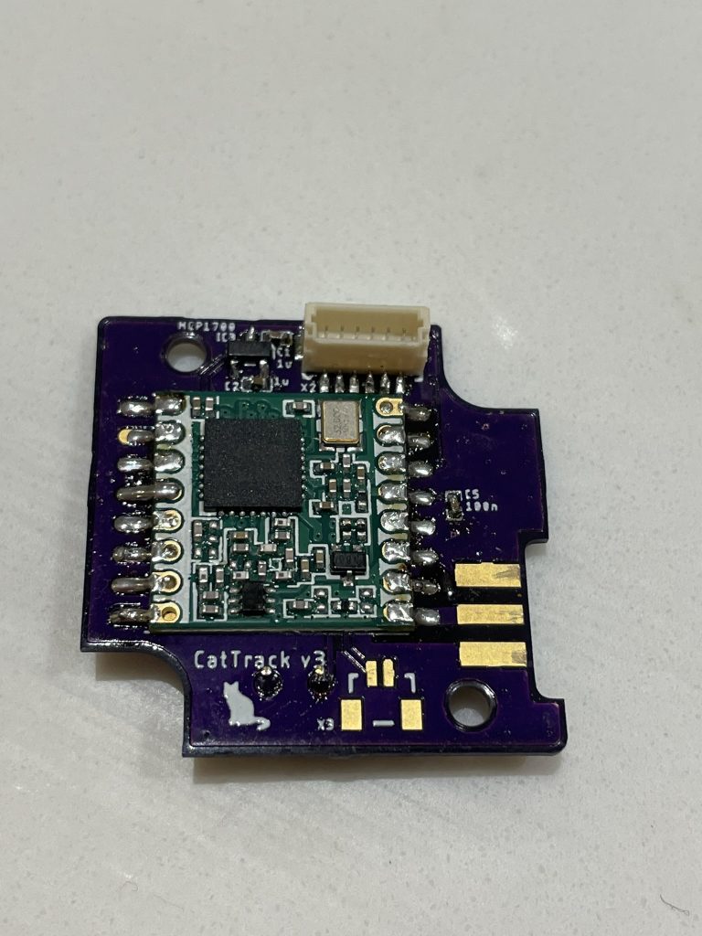
I just need to start work on the basestation. The small PCB discussed in this post goes on the cat’s collar. I need a ‘basestation’ PCB that will allow me to walk around and attempt to home in on the cat. For the previous version of CatTrack I made my own complete custom PCB, but this time I think I’ll do it a little differently.
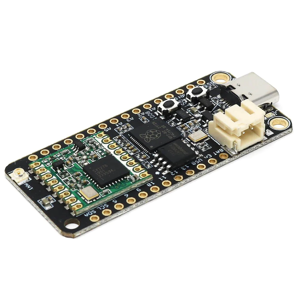
The two boards above are both available at The Pi Hut. The one on the left is a Challenger RP2040 LoRA board. It is a PCB with a Raspberry Pi RP2040 microcontroller on it, connected with the exact same HopeRF module I am using. I’ll be able to program the RP2040 to interface with the module and talk to the collar on the cat.
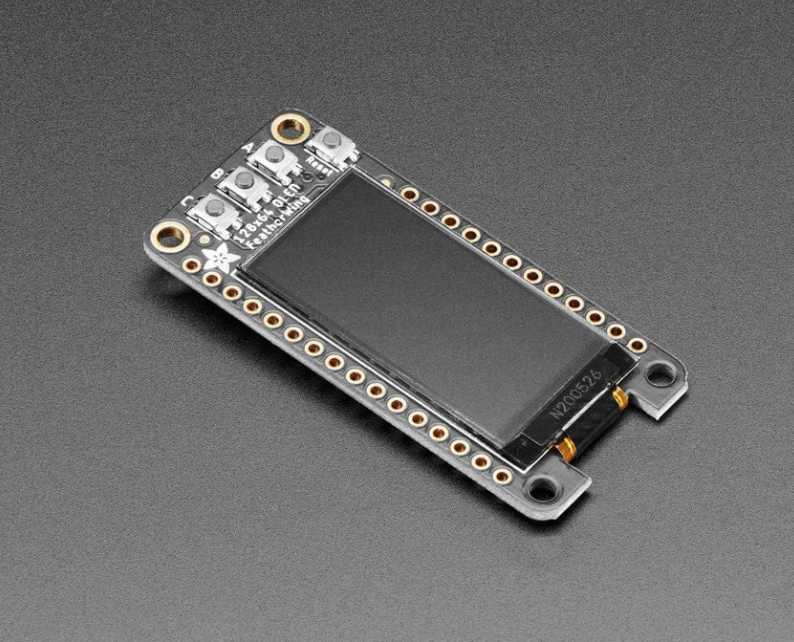
The board on the right is an OLED display that follows the same ‘feather’ form factor. This will solder on to the Challenger board and let me create a user interface for the basestation.
I’ve never used a Raspberry Pi RP2040 or an OLED display before, so I’m quite looking forward to tinkering with them.
Phew! I think that’s all for now!
Keep up the good work! I have a regular reminder to come back and check this website as it seems to be exactly the sort of thing I was looking for, but could never find.
It’s above my skill level to create something like this, but I’m capable of following along!
https://www.reddit.com/r/Lora/comments/17le6qp/comment/k7fp4by/?utm_source=share&utm_medium=web2x&context=3
This is the LoRa test 24km for a +17 dBm drive, committed during the evening of 1/11/23
Keep it up Andy! Let this comment be a reminder for you to keep motivation high 🙂
Glad to see you continue improving CatTrack
Looking forward to see your next post.
Woo thanks! I’ve been doing a load of work on it and (spoiler alert) have managed a range of 24 kilometers (albeit in very fortuitous circumstances). I’m going to get it basically complete and do a mega post about it I think. 🙂