It’s been a couple of months without an update, but I have been busy with CatTrack. I’m currently waiting for oshpark to send back an issue 2 PCB.
The only real change from the issue 1 PCB to the issue 2 PCB is a change in voltage regulator. I have spent a long time over the last couple of weeks scalpeling my existing board and isolating everything in order to measure how much current each of the devices on the board is consuming.
I initially measured the current consumption of the whole board with everything in ‘sleep’ mode as 3.5uA. This didn’t really add up with what I expected, so I isolated each device in turn (MUCH easier said than done!) and measured the current of the PIC, RF95W and regulator seperately.
I started with the PIC. There are plenty of guides around the Internet detailing how to reduce the current consumption of a PIC to a minimum. Microchip themselves have a good guide.
Fundamentally, you want to:
- Not have any floating input pins. Set them to output and drive them low or high, or pull them down with an external resistor.
- Don’t use potential dividers on input pins (see my previous post for how I designed a circuit to switch in a potential divider such that it didn’t consume current when not used).
- Turn off all unused peripherals (the ADC/FVR etc)
- Ensure you are using low powered oscillators when in sleep (not the main oscillator).
I spent a little while chasing around why when I went into low power mode it took a few seconds for the current to gradually drop. I found that the MISO pin was being ‘let go’ by the RFM95W and as such effectively turned into an unterminated input on the PIC. I solved this by driving the line low from the PIC when sleep mode is entered.
All of the above got me down to a 490nA consumption on the PIC. This is in sleep mode with a low power timer running, set to wake the PIC once every 10 seconds to check for incoming transmissions from the base station.
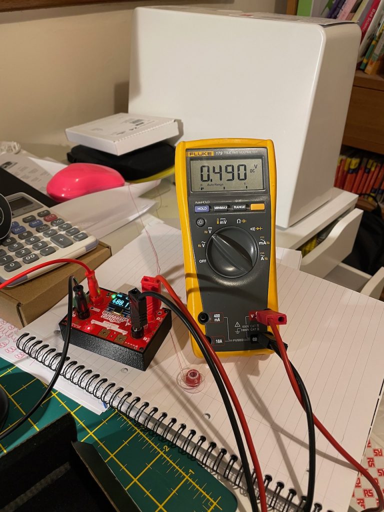
490nA measured using my current ranger. I had to isolate the PIC from the rest of the circuit to make the measurement (this was a huge pain… I made it easier on the issue 2 boards).
That’s the PIC sorted. For the RFM95W I am simply using the low power mode, entered via the SPI bus.
There is however a bug I discovered with the RFM95W (presumably also with the SX1276) which stops it entering low power mode properly if the first command you send is to enter LoRa mode and SLEEP mode simultaneously, i.e. writing 0x80 to the OP_MODE (0x01) register. I found that on several occasions this wouldn’t properly put the RFM95W / SX1276 into sleep mode and current consumption remained high.
The solution I found was to first write 0x00 to the OP_MODE register (i.e. FSK and SLEEP mode), before then writing 0x80 to OP_MODE (i.e. LoRA and SLEEP mode). The device always correctly entered low power sleep mode once I discovered this.
I would imagine this bug will be present in other Semtech SX127x devices too.
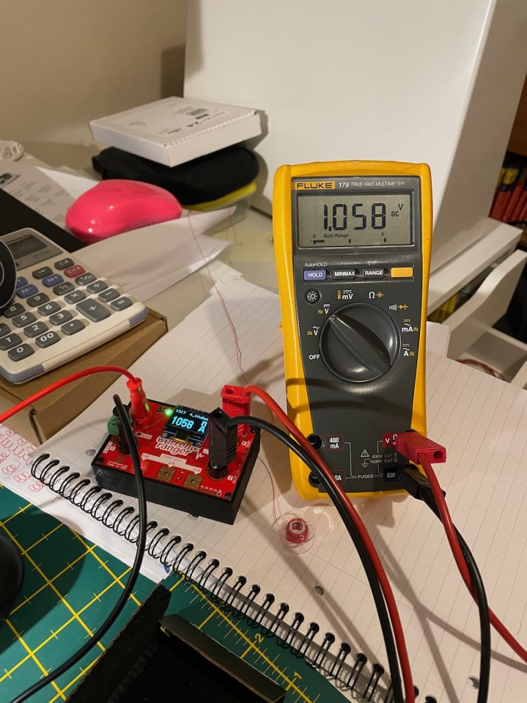
I measured the consumption of the RFM95W to be 1.058uA in sleep mode. The SX1276 datasheet quotes somewhere between 0.200uA and 1.000uA for sleep mode, but there are a few other devices on the RFM95W in addition to the SX1276 which will be consuming current.
This brings us to a total of 1.548uA. This is at odds with the measurement I made of the complete board which was 3.5uA.
To cut a long story short, the missing current came down to the voltage regulator I’d chosen. The quiescent current consumption of the regulator was a (comparatively) massive 1.9uA. To solve this, in the issue 2 board I’ve replaced the MCP1700T regulator with a TPS7A0230PDBVR. This quotes a quiescent current draw of just 25nA! One thing I will need to do is change my nominal board voltage from 3V3 to 3V0. This is because the dropout voltage of the TPS7A is a little higher than the MCP1700T. A lithium ion battery can get down to around 3.5V. Dropping my board voltage down to 3.0V gives me a 0.5V overhead for the dropout voltage (the difference between the input and output voltages of the regulator). The TPS7A requires at least 0.3V.
In order to be sure that this new regulator would fix the issue, I ordered some and wired them into the existing board. This was a bit of a mission given the completely different pinout between the two devices, and the fact that the device is only 1.75mm x 3mm.
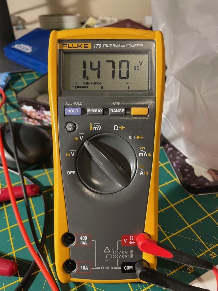
The result of the complete board consumption with the new regulator and new board voltage… 1.47uA in sleep mode. Hooray! A really decent improvement over the 3.50uA we started with. It sits in this state for 10 seconds, then wakes up for 60ms to check for transmissions, before quickly going back to sleep. More on that in the next post.
(Note that the current ranger is converting a current measurement such that it can be read by multimeter in voltage mode.)
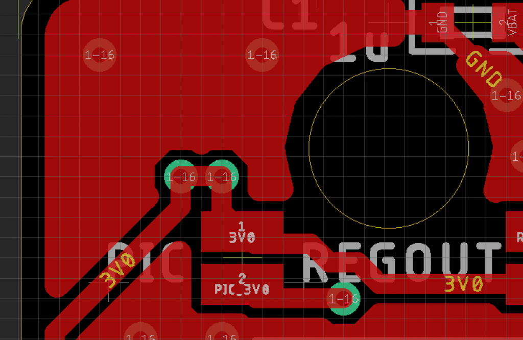
I’ll now wait for the issue 2 boards to arrive from oshpark and hopefully I’ll get the same result as the 1.47uA above. I’ve learnt my lesson with the issue 2 boards and made it much easier to isolate each part of the circuit with little solder blobs.
In normal operation there is a blob of solder on the little 3V0 and PIC_3V0 copper areas, joining them. However I can now easily isolate the main 3V0 net and the PIC_3V0 net, if I just want to measure the PIC current consumption.
Another update when I’ve played with the issue 2 boards!