I was a little premature with my previous post. I can’t quite draw the schematic diagram yet – I need to work out the antenna!
Texas Instruments have produced an excellent guide, examining a number of different types of antenna for embedded applications. The table below summarises the pros and cons of a number of different antenna solutions and is taken from that guide.
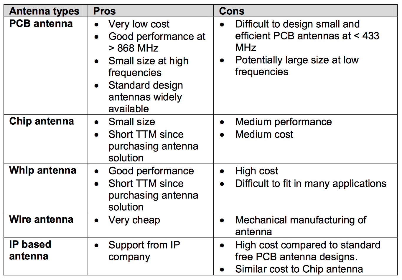
The antenna choice goes hand-in-hand with the frequency choice. Technically, using the CC1125 I can transmit anywhere from around 160 MHz to 1 GHz. However, in the UK I can only really choose from the 433 MHz or 868 MHz frequency bands as these are the bands I can transmit on without a licence.
A critical parameter in antenna design is the wavelength (SI unit: λ). The wavelength at 433 MHz is around 69 cm. At 868 MHz it is around 35 cm. One of the simplest antennas you can make is a dipole. The full length of the dipole antenna λ/2, so for 433 MHz that’d be around 35 cm and for 868 MHz it’ll be 18 cm. Given that size I clearly won’t be using a dipole antenna in my design!
As we’ve just shown, basic antennas at 868 MHz are around half the size of antennas at 433 MHz. Therefore it makes sense to use an 868 MHz antenna in my design.
After a good look at the TI guide, I’ve decided on a chip antenna – I reckon this will give me the best compromise between antenna size and performance. It’s important to note that the ground plane is really important with chip antennas. You can’t simply hook a chip antenna up to the RF output of your circuit on a tiny PCB with no ground and expect it to work. Looking at the Johanson 0868AT43A0020 datasheet, they have conducted their tests using the following board:
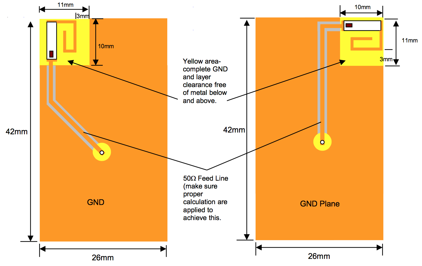
The entire board, including the ground plane, is important to the performance of the antenna – not just the chip antenna itself. I reckon that my board will probably be of similar dimensions to the Johanson test board above, so I will try to fit my chip antenna in a similar position.
It will be essential for me to ‘match’ the antenna into the output of my CC1125. If I were to simply connect the antenna to the CC1125 output, even with the correct ground plane, it would barely work at all. Antenna matching is the process of adding components to a design between the antenna and the RF output (in my case the CC1125) to ensure maximum power transfer from the CC1125 into the antenna. This is a fundamental job performed by an RF Engineer. I’m a lucky enough to have a VNA, so I’ll be able to match the antenna myself at home.
Now… onto the schematic!
2 comments