The issue 2 boards are here, I’ve soldered them up and tested them and the good news is that they match the performance I managed to prototype with the issue 1 boards (thereby rendering all the effort I put into making the supplies easy to isolate pointless, ah well!):
Sleep mode current  (10.00 seconds): 0.00147 mA
Active mode current (0.060 seconds): 8.97500 mA
This equates to an average current consumption of 0.0559mA, or 55.9uA. This means that a 200mAh battery will last (hopefully!) around 4.9 months.
This sleep mode / active mode time split is required because if we were to sit in receive mode (12mA) the whole time our battery would be dead in only 16 hours! Hardly ideal. To try and eek out more battery life, we turn off absolutely as much as we can for 10 seconds, then wake up for the smallest amount of time possible (60 milliseconds in our case) to check if anyone is transmitting to us. If they’re not then we go straight back to sleep for another 10 seconds. If they are then we activate the full receive mode to receive the full packet instead of going back to sleep.
The SX1276 has a mode called Channel Activity Detection (CAD). At the end of our 10 second sleep we tell the SX1276 to move into the CAD mode, described in the datasheet below:
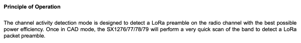
The radio automatically listens to what’s on the air for 33 milliseconds (12mA), then spends 28 milliseconds analysing what was received to look for signs of a transmission (6mA). We set DIO1 to the function of CAD_DONE in the code, so we simply sit and wait for that GPIO to go high, then read a register to establish whether or not there was a transmission present. If there was, we enter receive mode to receive it, if there wasn’t then we go back to sleep.
But… how can we be sure that the tiny amount of time we are in CAD mode catches the transmission from the basestation? Pretty simple really… we set the preamble length in the basestation to just over 10 seconds. That way, given that we sleep for 10 seconds in the collar, we can be sure that we will catch the transmission when we wake up because the transmission from the basestation is longer than 10 seconds.
The first packet of the transmission from the basestation to the collar contains 3 bytes (a quirk of the LoRa protocol means that there is nothing to be gained by transmitting fewer than 3 bytes). There are two operations supported, ping or beep. ping simply tells the collar to transmit back a reply to the basestation containing the battery voltage. beep does exactly the same thing, only it also causes the collar to beep, allowing you to locate the collar. Another bit of information transmitted from the basestation is the number of times to repeat this operation, from 1 to 255. This means that you can send a request to the collar telling it to beep 200 times, allowing you to spend some time trying to track it down. For each of these 200 beeps a ping reply will also be sent back to the basestation, giving you some indication via the Received Signal Strength Indication (RSSI) how close you might be to the collar.
This works brilliantly!
Not everything is brilliant, however.
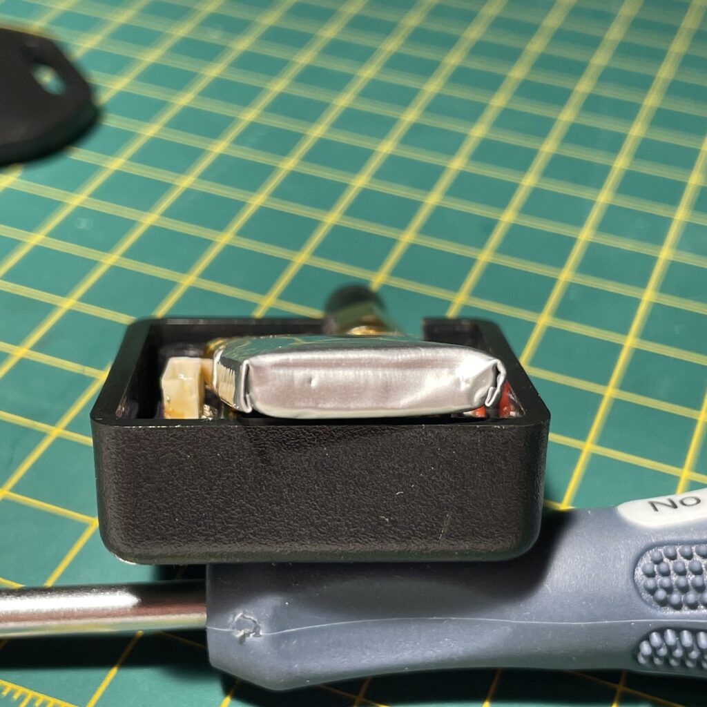
This is the LiPo battery after I left it for a number of months unattended.
It needed a charge. It’s a little hard to tell, but it has swollen badly. I measured the voltage of the battery and it was down to 1.4V. Much too low for a LiPo and charging it in this state could cause it to (in the worst case) explode. My attempts to charge it are almost certainly what has caused it to swell.
My previous experience with LiPos showed that they usually contain a protection IC to cut the load off once the battery drops to something like 3.0V. Clearly this battery didn’t contain this circuitry. There is some load protection circuitry on the cell, but clearly not under-voltage protection.
This LiPo is now dead, so how do we fix this in the future? I don’t really want to do another hardware respin, so the only choice is to fix it in softwareTM. This is a phrase that I use a lot in my professional life.
I already have the circuitry there to measure the battery voltage, so I think that I will measure the battery voltage every 100 odd seconds in the PIC and if it is less than 3.5V then I’ll put the device into its lowest possible power mode and never wake up again. This will still cause a current draw of around 1uA, so the battery will still eventually die, but hopefully this will put it off long enough such that I can get there and charge it before it drops too low.
I will be interested to see how quickly the battery voltage drops from 3.5V to a dangerous level with a 1uA current draw. If it still drops too quick then I’ll have to bite the bullet and modify the hardware and install a specific low voltage cutoff IC. Or I could put a P-type FET in and use the PIC to cut off the rest of the circuitry from the battery.
I’ll see how I get on!
This is awesome! I would like to know if I could buy one off of you. We’re looking for a tracker for our cat and similarly to you, I can’t find anything that seems to work as I would want to.
If there is anything else that I could do to help, let me know.
I know how to code in python if that helps 🙂
Patrick R.
Hi Patrick – I’ll have to have a bit of a think! At the moment I only have one, which is my development piece, I’ll have to see how many spare parts I have left over.