Well, the boards actually arrived several weeks ago, but I’ve only just got round to doing the soldering. As ever, I’ve ordered all my components from Farnell in the UK.
All of the passive components I’ve used are 0402 sized (0.5mm by 1.0mm). The advantage of components this small is that you can squeeze a lot into the RF sections of the board, most notably at the output of the CC1125. This decreases board size and improves the RF performance. You can go much smaller than 0402 – 0201 is the next size down, followed by 01005 – only 0.2mm by 0.4mm! Getting decent performance out of an inductor or capacitor that small will be difficult, so it’s a tradeoff between size and performance.
Whilst 0402 are solderable by hand, it makes life a lot easier if you have a microscope. Luckily I do! It’s not the world’s greatest microscope (it cost me about £200), but it does the job fine.
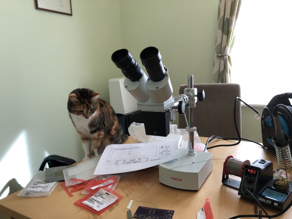
That’s Turnip, ‘helping’ me out.
I also need to buy a new soldering iron. The Tuloka 701C I have is pretty useless for what I want to use it for. The smallest of ground planes takes the heat away from the iron so fast that it’s a right faff to get a lot of components down properly. I need an iron with a much bigger thermal mass.
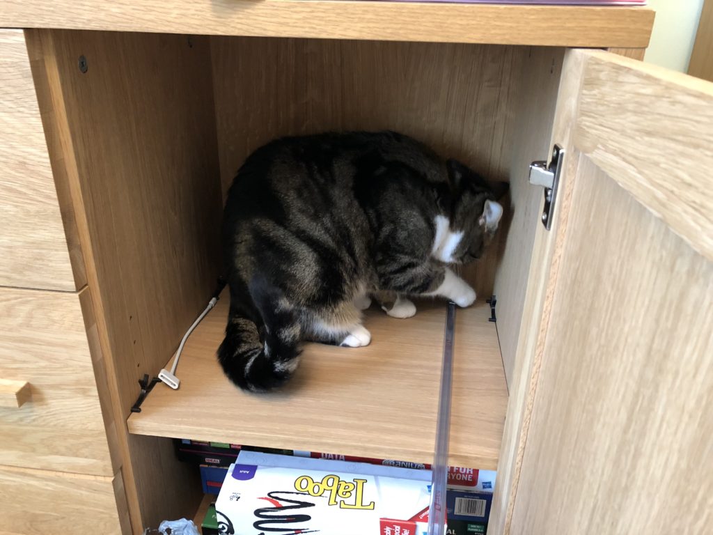
Buttons decided to ‘help’ too, by climbing into my electronics cupboard and pushing everything out.
The most difficult component to solder down is the CC1125. It has a ground paddle underneath which means that the board needs to be heated to get it down. You can’t get a soldering iron underneath the device when trying to solder it of course! There are plenty of videos explaining the process on YouTube – this one for example. I used that same technique with a hot air gun and it went down fine. Phew!
The rest of the components were pretty straight-forward thankfully, except for battling with my terrible soldering iron of course.
Here it is! (click to enlarge)
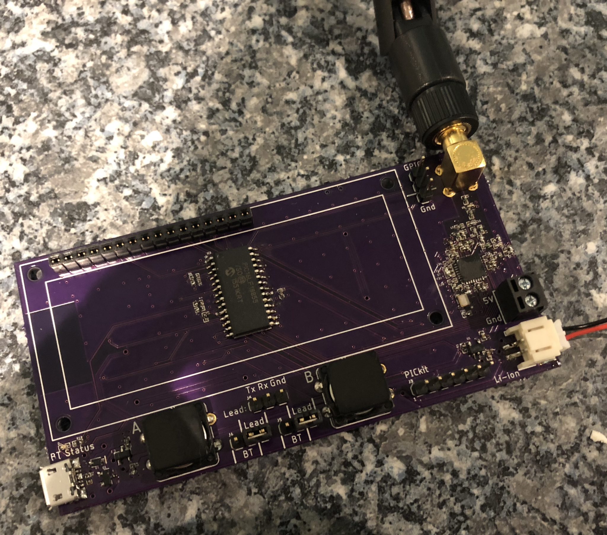
As you can see, the one thing I don’t have yet is the 16×2 LCD display (it will sit on top of the PIC in the middle). I ordered one from eBay China for a couple of pounds, but when it arrived it was the wrong colour (I ordered the traditional Green/Yellow display, but a Blue/White one arrived) and it didn’t properly line up with the mounting holes on the board.
When laying out the board I used the 16×2 LCD display part from SparkFun’s Eagle libraries, so I’ve just bitten the bullet and bought a display directly from SparkFun. This one, to be exact. Because SparkFun are a proper company, I know that the display is going to work fine and the dimensions on the datasheet etc. will be accurate. It’s cost me about 10 times as much as eBay China, but sometimes I guess you just have to pay for these things!
I’ve also just realised that I’ve left the ‘contrast’ input off the display. The VO pin should have a display drive voltage of around 3 volts on it, but I’ve left it unconnected. Oops. As soon as my display turns up from SparkFun I’ll have to hand solder some resistors on in order to fix that.
Now let’s get some code onto it and see if everything works!
One comment