The time has finally arrived, let’s test CatTrack on Buttons.
It doesn’t seem to bother him anyway!

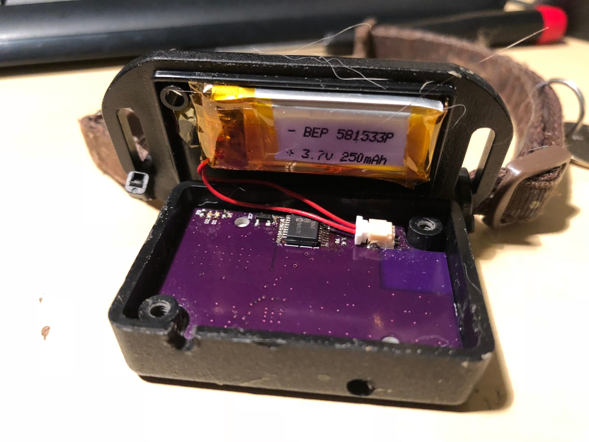
Open it up and you can see the li-ion battery (see Choosing a Power Source) connected to the back of the PCB with the PIC alongside it. The two LEDs are in the top left, although in order to save power they’re disabled in software, save for flashing once on power-up. You can see the light purple coloured area on the right of the PCB where the copper has been etched away for the antenna on the reverse. The battery sits on top of the ground plane just under this area.
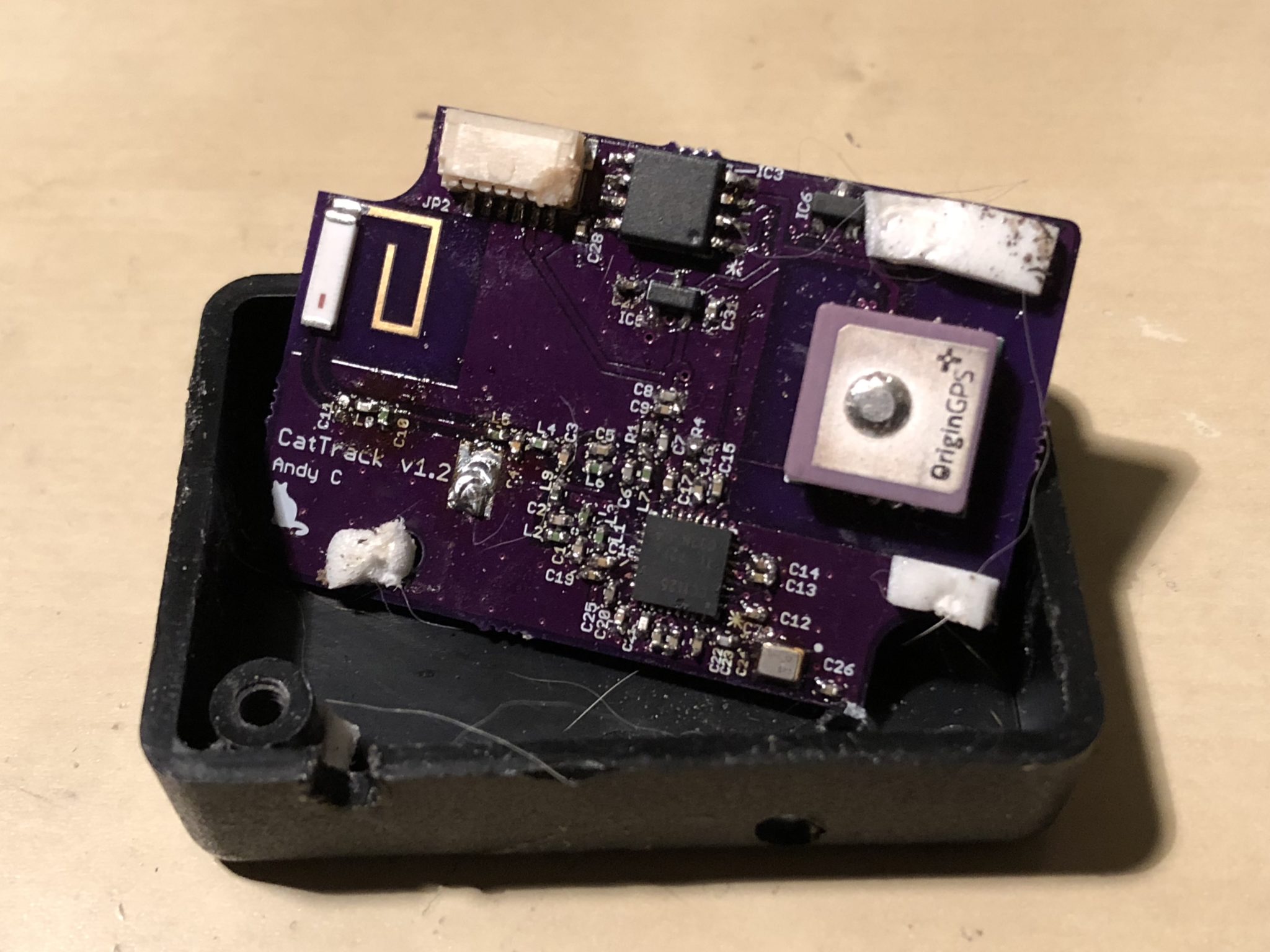
Flip it over and we can see the front of the PCB. The soldering looks a little shoddy, but bear in mind all of the small components are 1.0 x 0.5 mm and have been soldered by me by hand on the dining room table! The white sticky pads are used to hold the PCB off the bottom slightly such that the GPS antenna (the thing with OriginGPS written on) doesn’t contact the plastic.
In order to allow me to communicate with CatTrack ahead of designing the basestation unit, I’m using a CC1125 development board. This allows me to transmit and receive arbitrary packets to/from CatTrack directly from my PC, simulating the basestation. Annoyingly TI’s software doesn’t seem to support macOS, so I’ve fired up my Windows machine.
The interface looks like this:
![]()
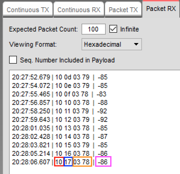
Zooming into the radio packets I am transmitting, we can see the following:
![]()
They are broken down thus:
- The message type (see Writing the Code for the list of message types I’ve defined). 0x03 is Beacon Mode, so I will expecting a short message back from CatTrack telling me the battery voltage.
- The message counter. Because I haven’t yet designed the basestation, I’ve hard coded this to ‘1’ for the time being and commented out the RF-replay checks in the CatTrack code.
- The number of replies to send. This tells the collar to send back 24 (0x18) battery voltage messages.
- Some check bytes. I’ve got two bytes free at the end (the encryption is donein 64-bit blocks), so I’ve arbitarily filled these with 0x0a and 0xec. The collar checks these bytes after decrypting the transmission to ensure it decrypted correctly.
Clearly the encryption isn’t yet turned on – I’ve commented that out in the code too. It’ll be too difficult to use the encryption from a development board. I’ll switch it on once I’ve designed the basestation.
CatTrack sits in its low-power sleep mode most of the time, waking the receiver up once every 16 seconds. Therefore in the worst-case scenario, I’ll need to send 32 messages – one every 500ms in order to ensure that CatTrack receives a message when it wakes up.
Let’s switch to the ‘Receive’ tab and see if we receive anything back…
Hurrah!!! This decodes thus:
- Device ID. This is a function of how the CC1125 operates. 0x10 is the the device ID of the basestation, so all other CatTracks in the vicinity know to ignore this message.
- Message count. I requested 24 (0x18) replies, so I’ll get 24 replies, 0x00 to 0x17.
- Battery voltage. I’ve coded this in BCD so it’s easy to read in hex. This means the battery voltage is 3.78V. Plenty of life left!
- Received Signal Strength Indicator (RSSI). This tells me the power that the signal was received at, in dBm. The lower the number, the further away Buttons is. It’ll range from around -125 dBm to -30 dBm.
Now that we know we have plenty of bttery life left, let’s send a ‘GPS position request’ and see what comes back. The message to be sent from the basestation to CatTrack is exactly the same as the 0x03 beacon request above, but 0x03 is replaced with 0x01.
At first, this is what the collar sends us back: 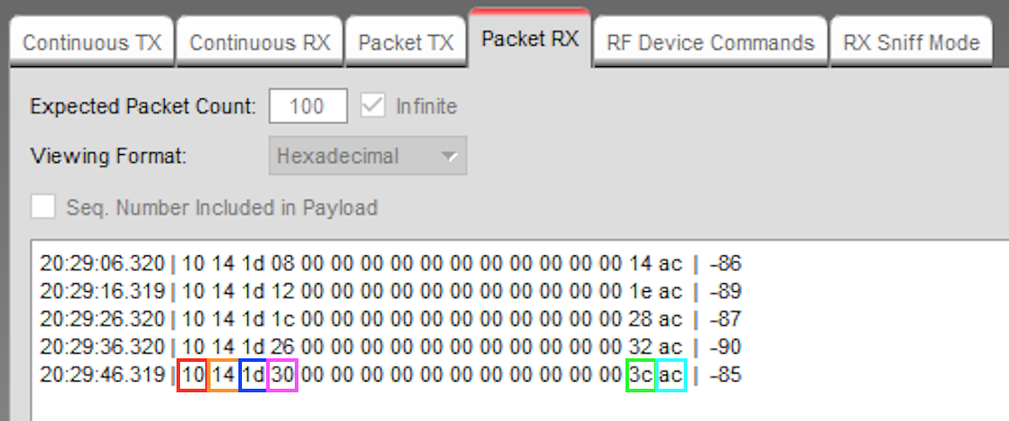
- Device ID. As before.
- Hours. 0x14 is 20, so 8 pm.
- Minutes. 29 minutes past the hour.
- Seconds. 48 seconds into the minute.
- Counter. Every GPS message from the module is counted. We only transmit one module every ten seconds, so this counter increments by 10 each time.
All of the zeros in the middle is the position information. We’ve not yet got a GPS lock so they’re all zero. We wait a few minutes, and then…
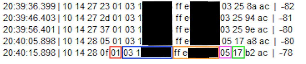
We’ve found Buttons!!! (I’ve blanked off the last 24 bits of each latitude and longitude)
- GPS quality. 0x01 indicates that we have GPS lock.
- Latitude. This is a signed 32-bit integer, in the decimal form ddmm.mmmm. We multiply by 10000 before sending. 0x03100000 translates to 51 degrees, 38.0224 minutes.
- Longitude. A signed 32-bit integer in the form dddmm.mmmm. Again, multiplied by 10000. 0xffe00000 translates to -2 degrees, 9.7152 minutes.
- The number of satellites we’re locked on to. Five in our case.
- The Horizontal Dilution of Precision (HDOP). We use this to assess how accurate our fix is. The lower the better. Anything less than 2.0 is good. Less than 3.0 is generally ‘ok’. 0x17 equates to 23 which means an HDOP of 2.3 (we multiply it by 10).
I’m really happy with how CatTrack is performing. Currently it looks like I’m going to have many months of battery life as the Li-Ion battery has only dropped from 4.2 V to 3.8 V in around 6 weeks.
Now I need to ditch the CC1125 development board and get on with making the basestation! That way I’ll be able to turn on the encryption and RF replay protection. I’ve quite a few ideas on how to implement the basestation too which I’ll share in a future post.
I’ll do some tests to see what kind of range I’m getting too.
I need to make sure I keep the momentum up. Now that CatTrack is working (albeit with a development board as the basestation), it’s tempting to take my foot off the gas, but I don’t want to do that, I want a full solution, including the basestation!
I’m glad you are continuing to post your progress. I can’t wait to see your post about the base station. You’ve done a great job
You used a PCB antenna (433MHz) 🙂
I’ve been looking for a simple example without success.
Can you (also hand-drawn) publish a layout with the dimensions?
I’m actually using 868 MHz, rather than 433 MHz. This page contains the info on the antenna I’m using – it’s a Johanson chip antenna – there’s a link on that page to the antenna data sheet with dimensions etc. Bear in mind that you will need to match into it, as the PCB size makes a massive impact on the antenna match.
Congrats on building the system! This is exactly what we were looking (and couldn’t find) before we opted for the loc8tor option.
What is the weight of the device on the cats collar?
I’ll weigh the collar as soon as he comes in! 🙂
He’s in! The weight of the complete device, including the collar itself and tag etc is 37 grams.
I enjoyed reading about CatTrack and I learned a lot. However, I tend to cringe a bit when I see battery operated wearables (or any battery operated device in close proximity to skin) without a fused connection close to the cell. Did you consider this for this design? Thanks.
Good point Bryon. I’ve tested the lithium ion cell protection circuitry and it does correctly shut off the supply when shorted, but a small inline fuse would add extra protection. I’ll bodge one onto the board the next time I charge the battery – thanks! 🙂