There are a lot of posts to trawl through in this blog if you’ve not followed it from the beginning. Hopefully this summary makes everything a bit clearer…
The first thing I did was to have a look at other cat tracking products on the market. I found that they all have a big flaw… battery life. I wanted GPS level accuracy and a battery life measured in months. Nothing on the market offered that, so it was down to me to design it!
I quickly ruled out a constant cellular connection, favouring a narrow-band RF design that spends the majority of its time in a deep sleep mode.
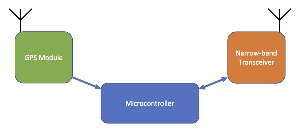
Next was to look at the main building blocks of the design, the GPS module, microcontroller and RF transceiver. I had a think about how which communication protocols would tie everything together.
Once I’d worked out the main elements of the design, I needed to start choosing components. First was the microcontroller. I knew it’d be a PIC as I’ve a lot of experience working with them, but which one?! I looked into the PICs that were available, and explained why you should never buy a PIC 16F84!
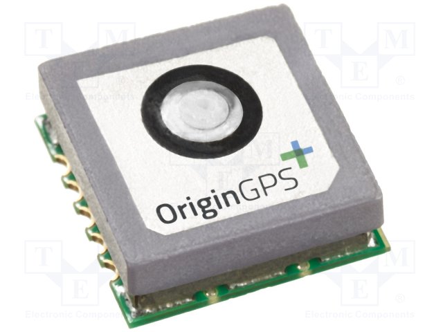
Now the microcontroller had been chosen, I needed a GPS module. I looked at several small GPS modules, before settling on an OriginGPS module – the smallest module on the market with an integrated antenna.
Then it was time for the last building block in the design, the RF transceiver. I looked at Bluetooth 2/3, Bluetooth 4, LORA, and raw FSK, before settling on FSK and a transceiver IC from TI, chosen simply because it has the highest FSK sensitivity on the market.
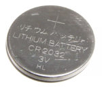
Next task was to choose a power source. I examined the current consumption of all the elements in the design, before looking for suitable batteries to power it.
The final part of the design was the antenna. Clearly I couldn’t have had a huge monopole antenna sticking up from Button’s head. I needed something small and discrete. I looked at TI’s excellent antenna design guide and went into some antenna theory and touched on antenna matching.
Before getting to work on the schematic I had to be clear how the collar was going to work:
- The collar initially sits in a ultra-low-power saving mode, waiting to receive a message from the basestation via the narrow-band transceiver.
- The user sends a message from the basestation to the collar, requesting the cat’s current GPS position.
- The collar receives this message and instructs the GPS module to turn on.
- As soon as the collar has a GPS fix, it sends the location information back to the basestation, using the narrow-band transceiver.
- The collar then switches back to its ultra-low-power saving mode.
Now that I’d selected all my components, it was time to draw the schematic.
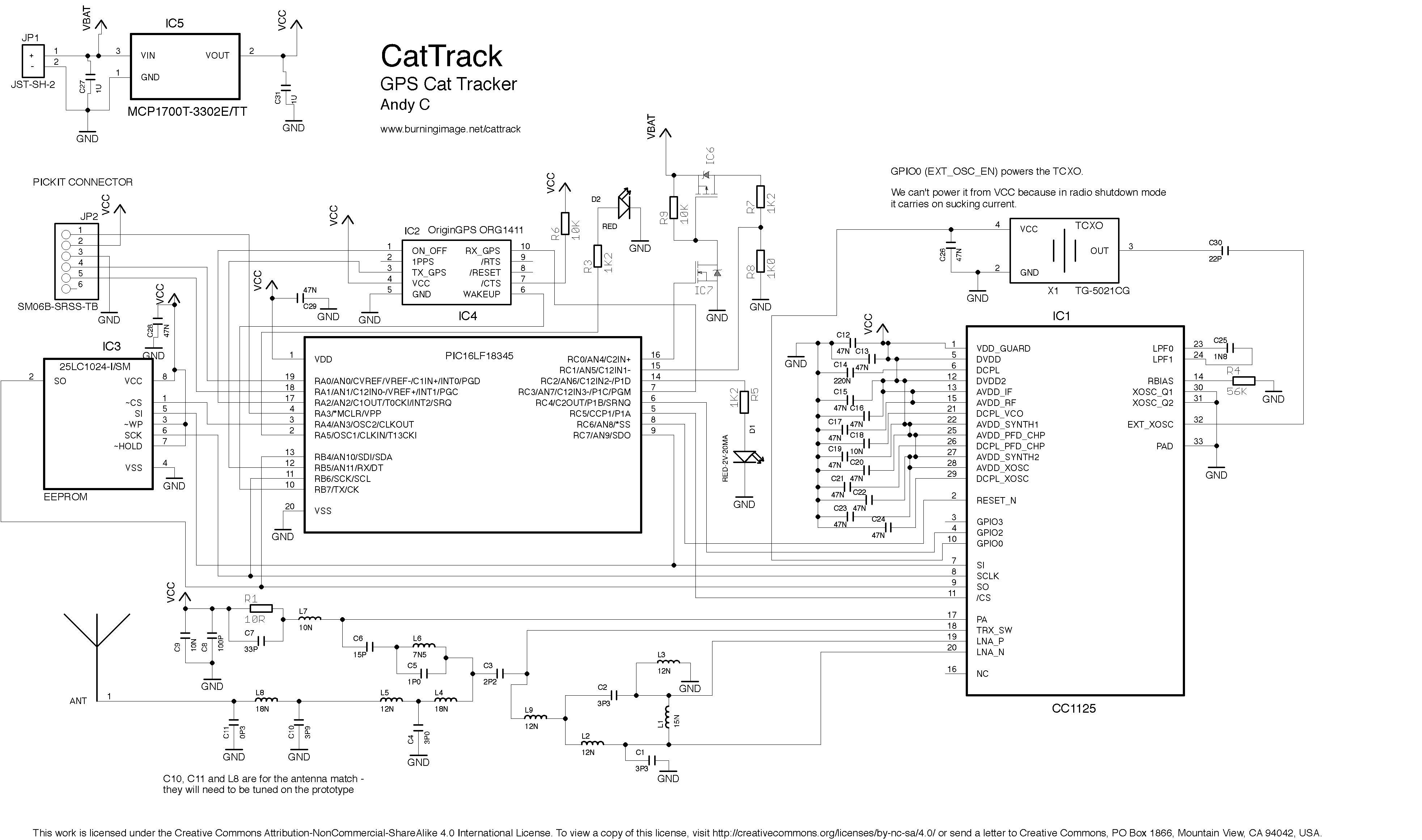
I examined the various parts of the schematic, explaining in detail what each element was responsible for.
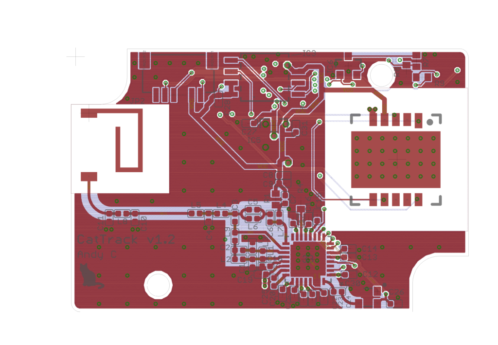
I spent many days looking for an enclosure that would fit on Buttons’ collar. I eventually found one made by Hammond. Once I had the enclosure, I could design the PCB to fit it. I was using my favourite design tool, Eagle.
Whilst waiting for the PCBs to arrive I got on with writing the code. I thought about the different operation modes, the format of the packets I was transmitting and how I would encrypt the data and prevent RF replay attacks.
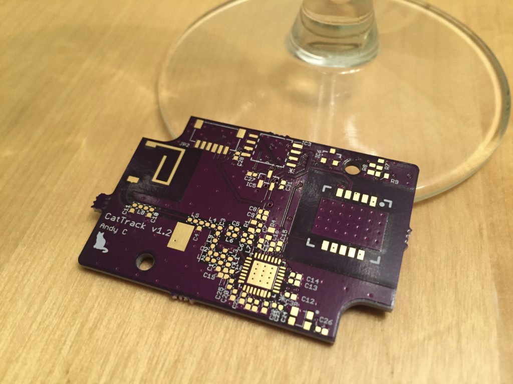
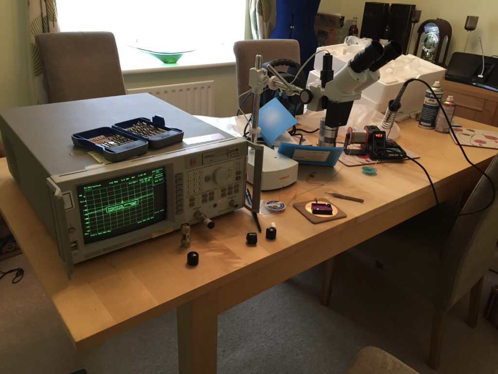
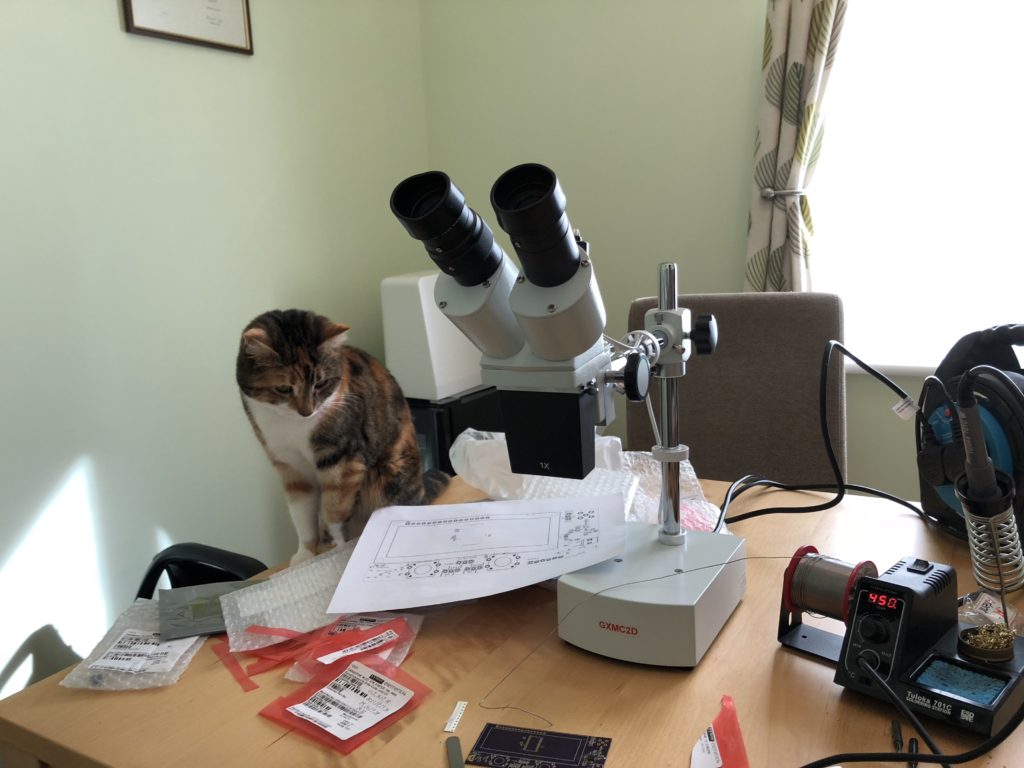
After a few weeks’ waiting, the PCBs finally arrived! It was finally time to solder them! This post also goes into detail on matching the antenna, with lots of pretty pictures. I also got to use my new microscope!
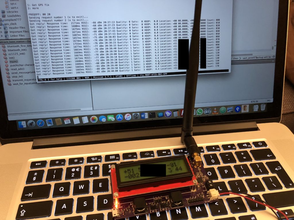
Obviously I’ve not yet designed the basestation, but I could test the collar using a TI development board to simulate the basestation, so that’s what I did. And guess what… it worked!!
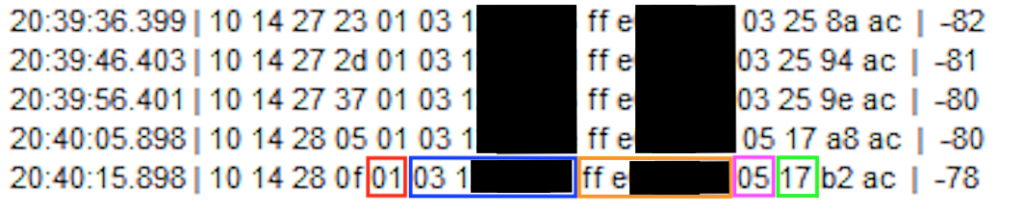
I could see the collar position arriving, encoded, back at the TI development board! This post also goes into detail looking at the RF protocol and what each transmitted byte means.
So far I’d written all of my PIC code using the (non-free) CCS PIC compiler. I wondered just how much bigger my code would be if I ported it to Microchip’s free compiler. The result was a bit of a surprise!
The time had come to replace the TI development board that I’d been using to talk to the collar with a properly designed basestation. I had to think about how the basestation would be powered and how I’d use it day-to-day. It obviously needed to have a screen and some buttons for user-input, but I also wanted to be able to communicate with the basestation remotely, from my PC. Read all about the design here.
![]()
Naturally, the next thing to design is the basestation PCB. During this design I also had to think about what to do when it’s impractical to implement 50 ohm track widths.
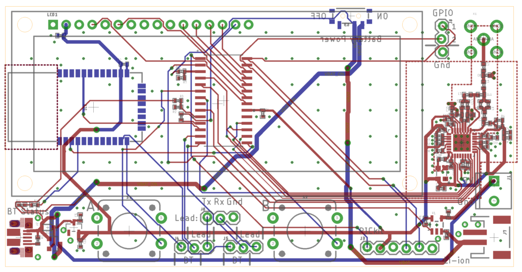
Once again, after a couple of weeks waiting by the letter box, the PCBs finally arrived and it was time to solder them! The only thing I was missing was the LCD display, as eBay China had let me down (who’d have thought…). I ended up ordering one from a supplier I trust – SparkFun.
In writing the code for the basestation I learnt a lot about using the CC1125 transceiver for long range communications. I initially thought that there was something wrong in my design, but it turned out to be a clock accuracy issue. Read all about it, along with some RF theory regarding long range communications using the CC1125 transceiver.
And after all that….. everything is working!!
Nice work! Some transceivers, like the popular sx1231 (HopeRF RFM69) has two bandwidth settings, one for the RSSI detection, which leads to AFC and then a separate (typ narrower one) for the actual packet reception. I.e., the same you are doing but integrated into the chip.
BTW, one issue with TXCOs is the power consumption. You seem to have it permanently powered, which draws several uA’s, at least for the models I’m familiar with. As an example, the latest LoRa radio chip (sx1262) has an enable pin that can be used to power the TXCO so it’s only on when the radio needs it.
Oops, I see that you are powering the TXCO from the radio chip, I had somehow overlooked that. Never mind ;-).
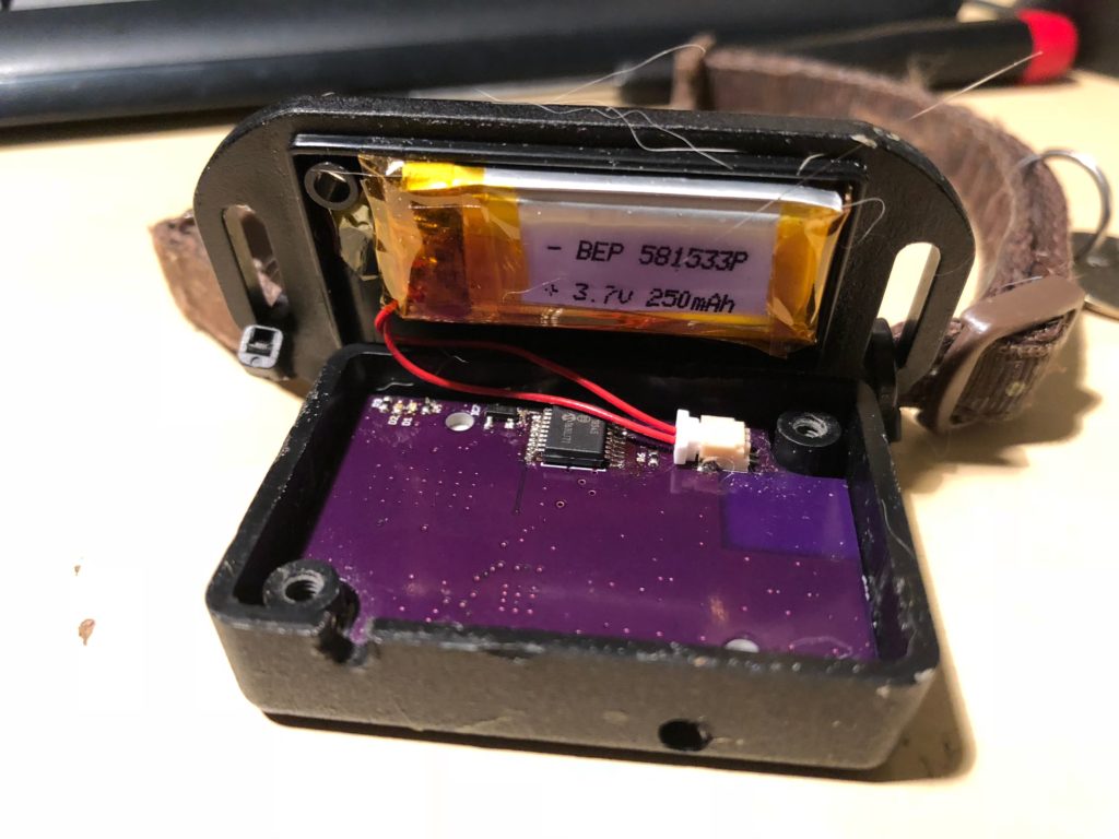
Now you need a “real” test: have someone go hide the collar somewhere in the neighborhood, and you have to track it down.
It’s funny you say that… Buttons has tested it multiple times by coming home without his collar! Thankfully CatTrack worked as I’d hoped and I was able to track it down. One time is was in a horrible muddy bush, and the second time in the middle of an allotment. Very satisfying to actually use CatTrack (sort of) for what it was designed for!
Question from a non technically educated person… What would it take for you to make and sell this as a product? If so, what would it cost?
It’d take someone with a bit of business acumen to help me out! I’m alright at the technical side of things, I can design electronics just fine, but as soon as it comes to anything to do with business I’m rubbish. I’m sure that a more business-savvy person could have taken CatTrack and turned it into a product, but unfortunately I’m just not that person.
I’d think that a product version of it would probably cost in the region of £150, given component costs, assembly, profit etc.
Maybe one day!
Hey, awesome project!! I saw that you’re working on a 2.0 version now, best of luck.
If I wanted to replicate your v1, skipping all of your crazy cool design work that you have to do initially and just order everything I need and putting it all together, how much would that cost? Do you have a BOM that I could see? Are you considering this open-source? No pressure of course, just thought it would be cool!
Hey GranolaHo..! Drop me an email on tribune.gadgets-9y@icloud.com and I’ll see what I can dig up to send over, 🙂