I’ve finally finished the CatTrack schematic, hurrah!
Click it to enlarge.
As a reminder, my plan is for the collar to work thus:
- The collar will sit in a ultra-low-power saving mode, waiting to receive a message from the basestation via the narrow-band transceiver.
- The user sends a message from the basestation to the collar, requesting the cat’s current GPS position.
- The collar receives this message and instructs the GPS module to turn on.
- As soon as the collar has a GPS fix, it sends the location information back to the basestation, using the narrow-band transceiver.
- The collar then switches back to its ultra-low-power saving mode.
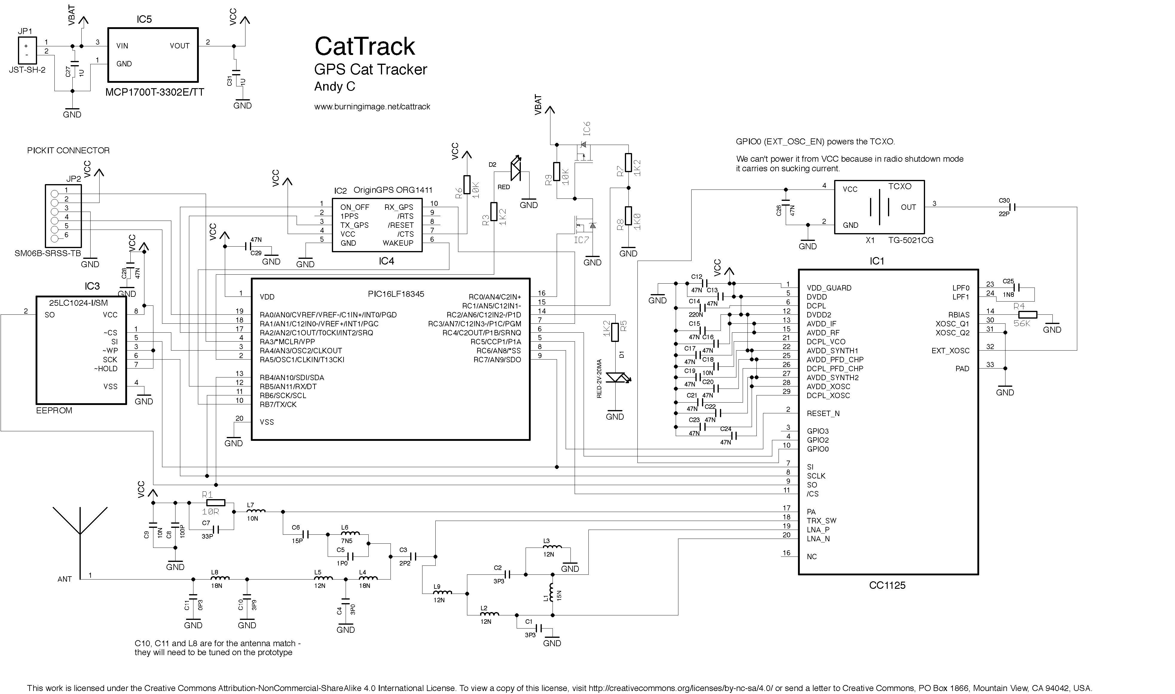
The schematic brings together all of the design elements from my previous posts. At the core of the design is the PIC16LF18345 microcontroller. Connected to this is the GPS module and CC1125 narrow-band transceiver. The GPS module communicates via hardware UART pins of the PIC and the CC1125 uses the hardware SPI pins. Also connected to the SPI pins is an EEPROM (IC3). My plan is that in the future I’ll incorporate a mode where the GPS position is periodically saved to the EEPROM, ready for later offline analysis.
The circuit is powered from a lithium-ion battery. IC5 regulates the lithium-ion battery down to 3V3 which is then used to power the rest of the circuit.
I wanted to use an ADC input on the PIC to measure the battery voltage and therefore tell me how much battery life is left, but there are a couple of hurdles to overcome. The internal PIC ADC reference voltage is 2.048 V. This means that I can’t feed a voltage into the pin higher than 2.048 V. The voltage of a lithium-ion battery is generally anywhere from around 3.5 V to 4.2 V.
Usually the way you’d overcome this is with a potential divider. Simply divide the battery voltage down and then feed it into the ADC pin. You can then compensate for the divided voltage in software. However… using a potential divider means that I will be needlessly wasting current. Not ideal for my ultra-low power design.
To get around this I’ve designed the circuit around IC6 and IC7. When I drive pin 16 of the PIC high, this causes the N-type FET IC6 to conduct, which pulls the gate of the P-type FET IC7 low. This has the effect of connecting the li-ion battery voltage to the top of R7, which combined with R6 divides the li-ion battery voltage down ready to measure it with the ADC. Phew!
Once I’m done measuring the battery voltage I’ll drive pin 16 of the PIC low, which causes the gate of IC6 to float high, thereby turning it off and disconnecting the battery from the potential divider and improving our current consumption.
I’ve connected a couple of LEDs to the PIC – I’ll use these to debug the board during development. I certainly won’t use them in the final code release as they would be needlessly wasting current.
The CC1125 transceiver requires a 40 MHz TCXO (timing crystal). This 40 MHz signal is the reference it uses to generate my 868 MHz transmissions. TCXOs annoyingly use a fair bit of current, in the order of a couple of milliamps. Again, no good for my low-power design. Obviously I will need to have the TCXO powered when I want to try and receive or transmit a signal, but when the whole board is in its shutdown mode, I ideally want to turn the TCXO off. Luckily, the CC1125 provides a GPIO pin for just this purpose. When the transceiver is on, the GPIO output goes high, and when the transceiver’s off the GPIO output goes low. It’s not really how you’d normally do it, but I’ve decided to power the crystal from this GPIO output. It seems to be able to sink the current required absolutely fine, so we should be ok.
All of the components on the output of the CC1125 pins 17-20 have been taken directly from the CC112x reference design from TI. These components act as a balun, tx/rx switch and match to 50 ohms. They can generally be left the same for any design that uses the same 868/915 MHz frequency band.
Three components that I will need to change are C10, C11 and L8. These match the 50 ohm CC1125 output into the antenna. I will need to use a VNA when I’m populating the board to ensure that the antenna is properly matched and therefore radiating correctly. If I leave those matching components as they are then it’s very likely indeed that the antenna won’t radiate at all, only giving me a couple of metres range when I should have hundreds of metres! I’m lucky enough to have a VNA at home to do this job myself.
So that’s it! The CatTrack schematic! Now I need to get on with choosing an enclosure and laying the board out.
One word on licensing… I’ve released the schematic under the Creative Commons Attribution-NonCommercial-ShareAlike licence. To find out what that means, click here.
One comment