My priority for the GPS module is the size and antenna. I’ve worked with external GPS chip antennas in the past and they can be a nightmare! Therefore for this project I’m after a small GPS module with an integrated antenna.
u-blox are generally my ‘go to’ company when I’m looking for a GPS module. Their prices are a little higher than random no-name stuff off eBay (obviously), but the documentation and support are second to none. I’m not sponsored by them, I promise.
Unfortunately it doesn’t look like u-blox sell that many modules with integrated antennas. Most of their modules are designed to be integrated into devices or systems that use external antennas. The one module they do have is the SAM-M8Q, which is 16mm x 16mm. We can do better than that, surely!
![]()
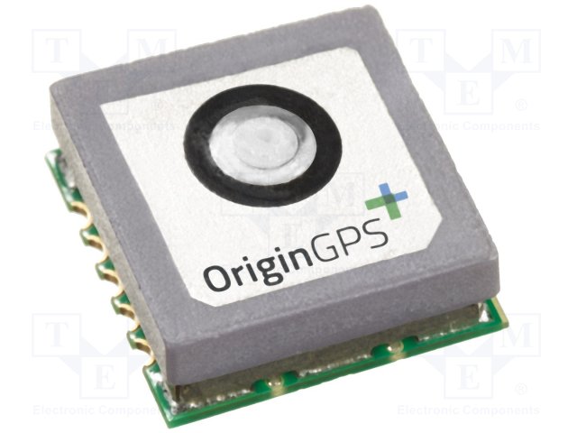
In order to find the world’s smallest GPS module, I Googled “world’s smallest GPS module”. It seemed to work and pointed me to the OriginGPS ORG1411 Nano Hornet. This module has an integrated antenna and is only 10mm x 10mm x 3.8mm! Although I’ve not used OriginGPS’s modules before, this is based on the SiRFstar IV chipset. A bit long in the tooth now, but absolutely fine for my needs.
The module has a bog standard UART interface which I’ll connect to my Microcontroller. In addition to this there are a few GPIO lines:
- WAKEUP – An output indicating whether the module is in high-power or low-power mode. I’ll connect this to the Microcontroller.
- ON_OFF – An input which allows us to switch the module between it’s ultra-low-power standby mode and full tracking mode. Perfect!
- 1PPS – An output which goes ‘high’ at the start of every second. I don’t need this so I’ll leave it unconnected.
As I planned previously, I’ll use the ON_OFF line to keep the module in it’s low-power mode for the vast majority of the time. Then when I receive a position request from the base unit, I’ll turn the module on, read the WAKEUP line to make sure it is on, then begin receiving position updates via the UART.
Looking at the application circuit from the datasheet, it looks like all I need to do is pull the /CTS line up to Vio with a 10k resistor to enable UART mode. I won’t need R5 or R6 – the pin will tolerate 3V3 so I’ll connect this line directly to my Microcontroller.
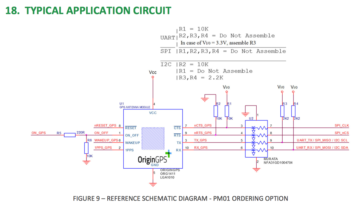
One thing that you do need to watch out for are the logic IO levels. I’ll be using the 3V3 variant of the ORG1411 (PM04 option), but even though Vcc on this version is 3V3, the IO output level on WAKEUP and TX is still only 1V8.
By default, the PIC microcontroller inputs are in ‘Schmitt trigger’ mode. Looking at the PIC16LF18345 datasheet below, we can see that the Schmitt trigger mode is not compatible with 1V8 logic – the ‘Input High’ voltage is 0.8 * 3.3 = 2.64V. We need this to be under 1.8V.
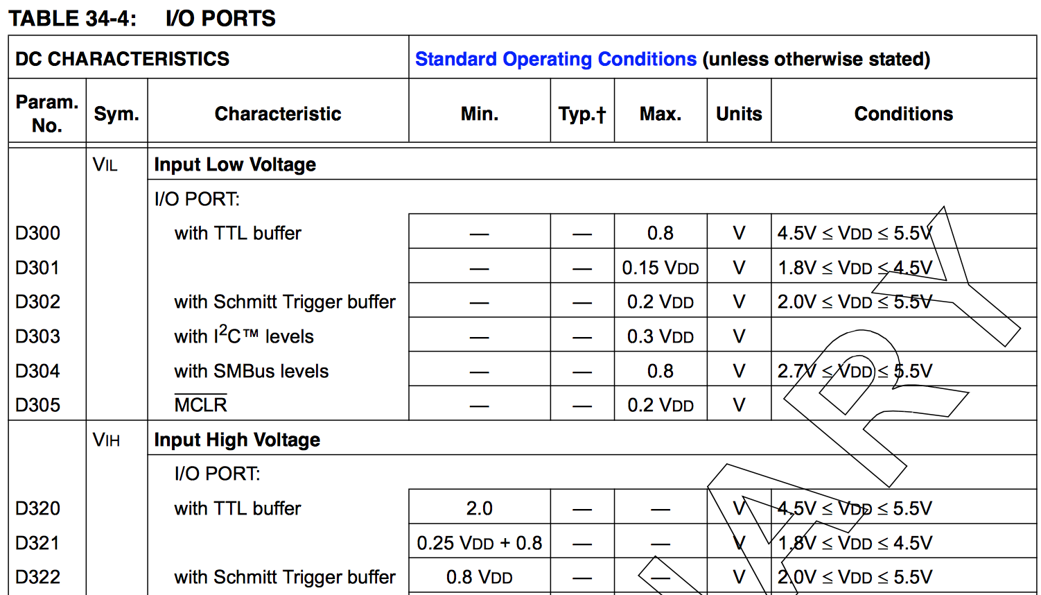
In TTL mode, the ‘Input High Voltage’ is 0.25 * 3.3 + 0.8 = 1.625V. Perfect! We just need to remember to switch our IO into ‘TTL’ mode when we write the PIC code.
GPS module – sussed!
2 comments