The last thing I need to work out before getting on with the schematic is which battery chemistry I’m going to use. The most important thing at this point isn’t necessarily identifying the exact battery I want to use, I need to just know the voltage, such that I can design the circuit to suit.
In order to work out the ideal battery chemistry, I need to work out how much each component draws, both in sleep mode and at its peak.
| Component | Current Draw in Sleep | Peak Current Draw |
|---|---|---|
| PIC 16LF18345 | 13 µA | 1.8 mA |
| Nano Hornet ORG1411 GPS Module | 18 µA | 47 mA |
| CC1125 RF Transceiver | 1 µA | 47 mA |
| 25LC1024 EEPROM | 1 µA | 5 mA |
This tells me that the total current consumption whilst sleeping will be around 33 μA, with a maximum possible peak current of around 100 mA. This peak power consumption assumes that we are transmitting at the same time as attempting to acquire a GPS fix.
All of the components I’ve chosen thus far run from 3.3 V. They’ll also run at 3.0 V if needs be, so if I can find a battery with a native voltage of 3.0 V then I won’t need a regulator.
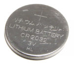
On paper, a lithium ion battery like the CR2032 looks ideal. It’s native voltage is 3.0 V, so no regulator needed, and the capacity is fairly good at around 225 mAh. In sleep mode, this will in theory give us over 6800 hours use – well over 9 months! However… the maximum current draw from a CR2032 is around 15 mA. This is much lower than the 100 mA I may need to supply, so that knocks that idea on the head!
Wikipedia has a really good page with a list of loads of battery chemistries, along with voltage and typical capacities. To cut a long story short, I sat on this site for several hours, but didn’t find anything that I liked or seemed to fit my requirements perfectly.
In the end I’ve settled on using a lithium-ion battery. This is the chemistry that pretty much all rechargeable electronics use these days. The high energy-density should be perfect for my needs. Another bonus with lithium-ion batteries is that they come in hundreds of different shapes and sizes, so I should be able to find one that fits in whichever case I end up using.
Lithium-ion battery downsides
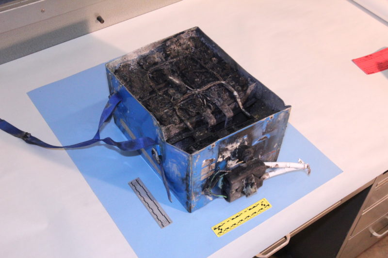
This is the lithium-ion battery from a Boeing 787 Dreamliner. I don’t want Button’s collar to end up like this!
Generally speaking, lithium-ion batteries catch fire whilst charging, rather than discharging. I don’t plan on adding any charging circuitry to CatTrack – it will be down to the user to switch the battery over every few months. I’m also going to ensure that the PCB is in a sturdy plastic enclosure such that the battery can’t be chewed/scratched or get caught on anything.
Voltage Regulators
Because a lithium-ion battery voltage varies from around 3.5 V to 4.2 V, I’ll need a voltage regulator to regulate the voltage down to 3.3 V. There are two basic types of voltage regulator: Linear and Switching. Linear regulators are by far the simplest to implement, but the drawback to them is that they are inefficient and can only step voltages down. When using a linear regulator, the current that the regulator draws from the input supply is the same as the current that your circuit draws from the stepped-down voltage. This means that the larger the difference in input to output voltage, the more inefficient the regulator is, and therefore the hotter it gets.
For example, if you used a linear regulator to power your 5V circuit from a 12V supply and your 5V circuit pulled 100 mA, the regulator will also pull 100 mA from the 12 V supply.
Switching regulators are far more efficient, they don’t get increasingly inefficient as the input voltage increases like Linear regulators do. The downside is that they are also far more complex and generate a lot of undesirable electrical noise. Stepping up a voltage is possible with a switching regulator, which is a huge advantage. For example you could power your 5 V circuit from a 1.2 V battery using a switching regulator. As is always the way with physics, you don’t get anything for free, so the current drawn from the 1.2 V battery will be around 4.5 times higher than the 5 V circuit draws.
Because my input voltage (3.5 V to 4.2 V) is very close to my desired output voltage (3.3 V), there is no point in using a switching regulator. The tiny efficiency gain at these voltages just isn’t worth the extra circuitry and hassle.
The dropout voltage is a key parameter in a voltage regulator. This is the minimum difference between the input and output voltage for the regulator to operate correctly. I need the dropout voltage to be 0.2 V maximum (3.5 V minus 3.3 V).
The Microchip MCP1700 fits my needs perfectly, with a very low typical dropout voltage of 178 mV!

Power source and regulator sorted!
WRT CR2032 you might consider a large cap (100uF or more) which can take a brunt of a short TX. Nordic Semi wrote a whitepaper on CR2032 life expectancy give short high power consumption bursts. It’s not great but not awful either.
WRT power regulator, IMHO it’s more important to focus on the quiescent current than the drop-out. The one you chose draws typ 1.6uA when idle while others (I like the TSP782 series) only draw 0.5uA. That’s a whole uA savings!
If you are concerned about the LiPo hazards you might consider AAA LiFePo4 batteries. I don’t know whether one would fit into your enclosure, but they’re a lot safer. Also, you might be able to get by without power regulator.
BTW: I’m surprised at how power hungry that PIC and that GPS module are in deep sleep! I’m used to the STM32L0 series which deep sleeps with a low-power time enabled at around 1uA and other GPS modules (such as the GlobalTop PA6H 15mmx15mm) sleeps at 7uA. You might consider adding a FET to turn that off when you don’t need it since in your use-case you’re going to do a cold-start almost all the time anyway.